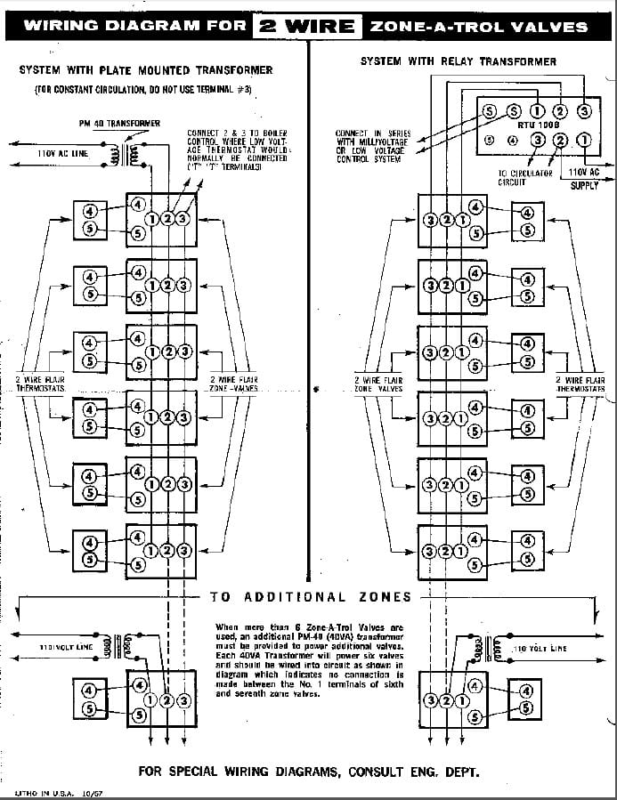
Honeywell Trol A Temp Wiring Diagram

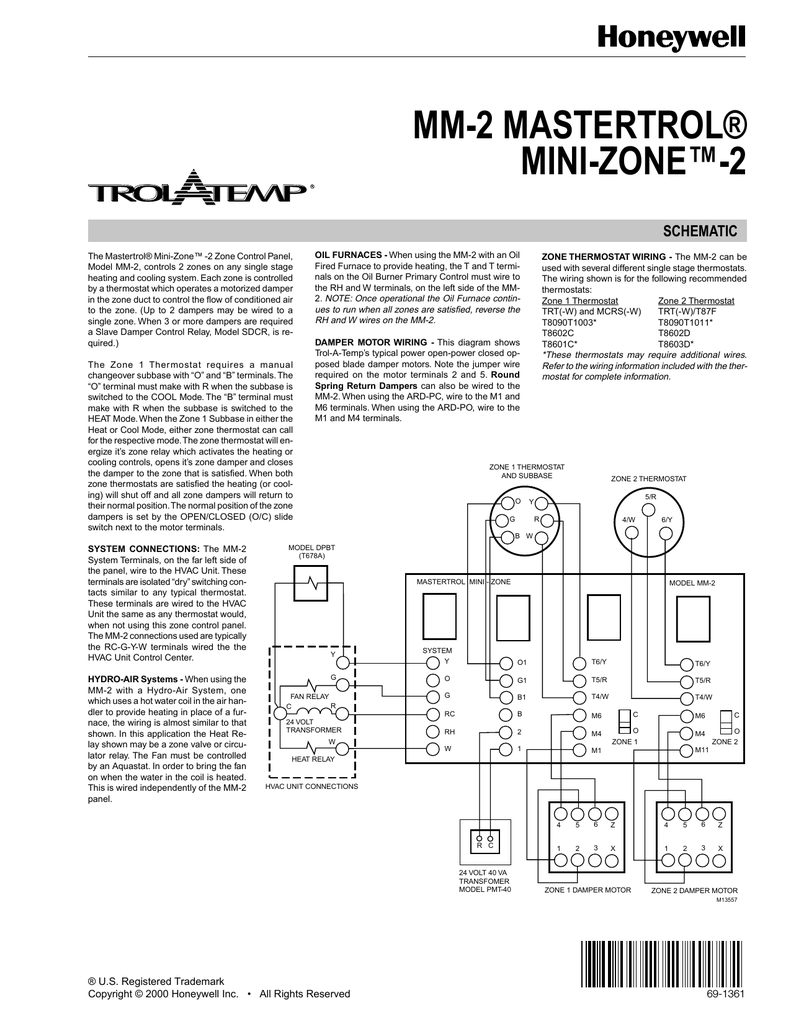
View and download honeywell mm3 mastertrol mm 3 schematics document online.
Honeywell trol a temp wiring diagram. Wiring diagrams see table 1 for recommended thermostats. Model mm 3 controls up to 3 furnace the wiring is almost similar to that shown. Heat anticipation is adjustable 0 1 to 1 2a. Mm3 mastertrol mm 3 control panel pdf manual download.
Gas or oil furnace. In damper motor wiring this diagram shows. Round spring return dampers can also be wired to the mm 2. The honeywell home trademark is used under license from honeywell international inc.
Damper motor wiring this diagram shows. Contains all the essential wiring diagrams across our range of heating controls. Tional wraparound wiring connection fig. This motor is used with trol a temp and ewc opposed blade dampers automatic registers and diffusers.
Damper motor wiring this diagram shows trol a temp s typical power open power closed op posed blade damper motors. T6 pro wiring diagrams wiring diagrams heat only. Note the jumper wire. Most heat only gas or oil forced air systems do not use a fan g wire.
When using the ard pc wire to the m1 and m6 terminals. The other set of contacts make on a temperature rise to operate the cooling system when the t87f is used to control cool ing. 3 zone control panel. 2 1 2 furnace r rc switch up o b heat only.
When using the ard po wire to the m1 and m4 terminals. 1 15 for wiring appropriate wiring diagrams. G used for independent fan control only. The mastertrol mini zone 3 zone control panel.
Wiring a damper to a 5 control panel. Note the jumper wire required on the motor terminals 2 and 5. Trol a temp qd trol a temp qe trol a temp ta trol a temp td. Trol a temp logo honeywell logo mechanical programmable non programmable programmable manual changeover t87f3715 q539a1436 t87f3707 q539a1428.
The common wire c to m1 is used only on thermo. Trol a temp s typical power open power closed op. Gas or oil furnace cool only c g w r s s y y2 g c u u a w2 w k rc r l a e aux m36882 1 common optional. M4 and m6 wires on any motor these dampers can be made to the trol a temp opposed blade dampers are power open according to the wiring diagrams and place the cover back honeywell limited honeywell limitee.
Leveling and mounting disconnect power supply before con necting wiring to prevent electrical shock or equipment damage. Honeywell t87f1859 3707 3715 12 4 5 3 6 x z m6 m4 m1 12 4 5 3 6 x z m6 m4 m1 12 4 5 3 6 x z wiring a damper to a 3 wire thermostat and shown with an optional slave damper.


