Honeywell Millivolt Gas Valve Wiring Diagram

Frymaster sm60 user manual robertshaw millivolt gas valve.
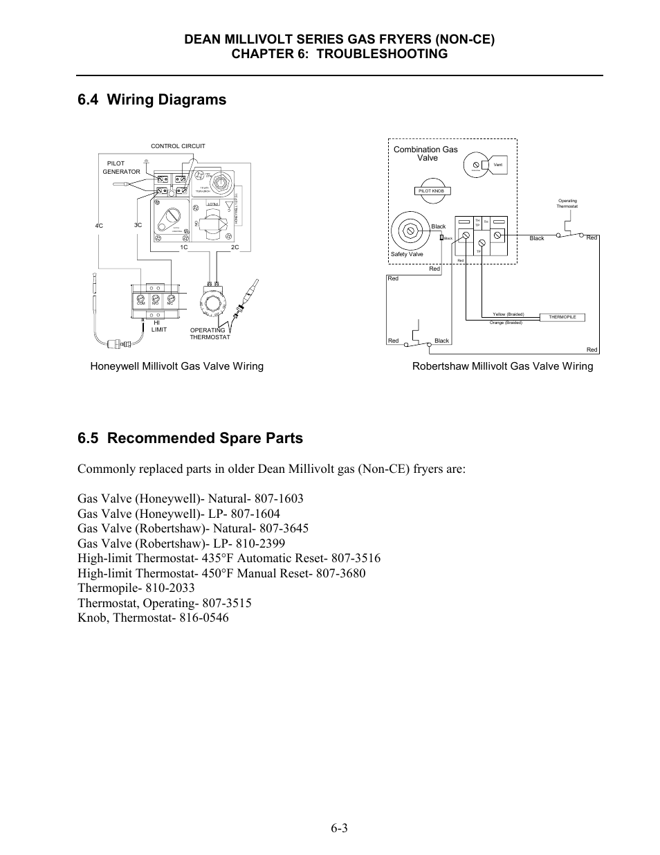
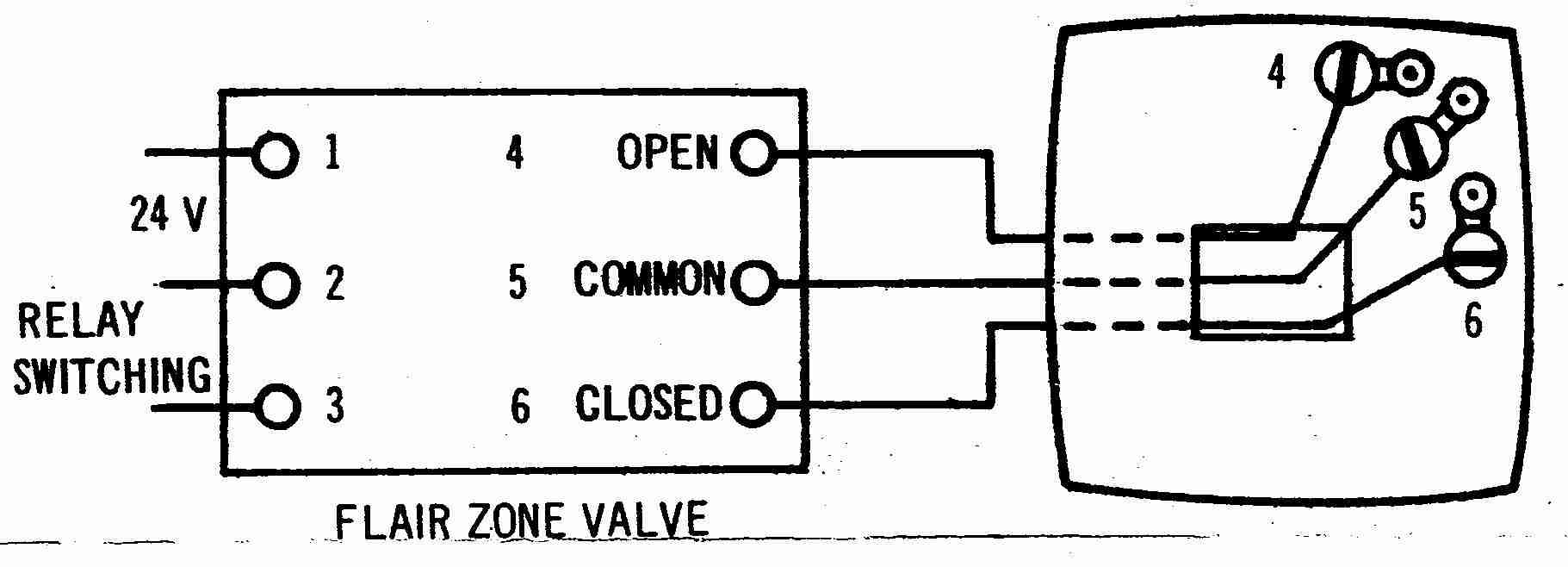
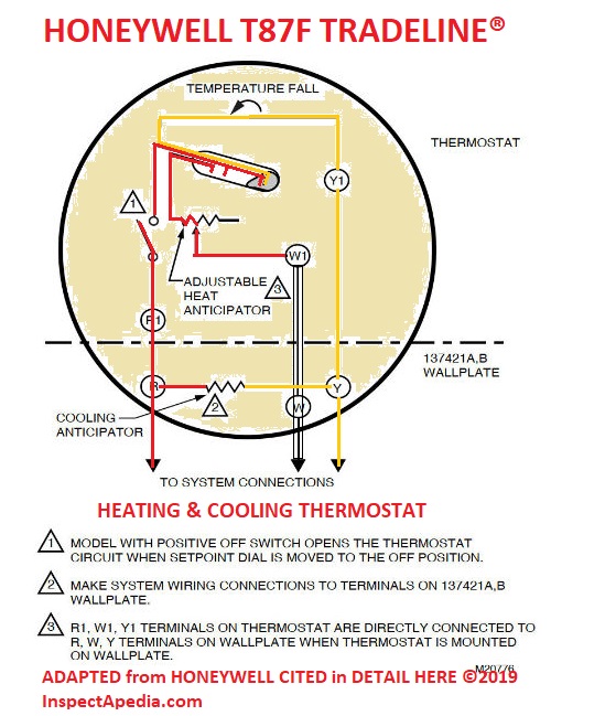
Honeywell millivolt gas valve wiring diagram. Millivolt thermostat wiring diagram gas valve wiring diagram collection wiring diagram rh visithoustontexas org honeywell thermostat wire colors honeywell zone. A wiring diagram is a simplified standard pictorial depiction of an electrical circuit. A manual gas shut off valve must be installed in the gas supply line ahead of the fryers for honeywell millivolt gas valve wiring. The millivolt gas valve system includes a gas valve quick drop out thermocouple thermopile millivolt thermostat and a pilot burner.
Wellborn collection of honeywell gas valve wiring diagram. Pilot off 4 0 0 3 5 0 3 0 0 2 5 0 2 0 0 operating thermostat hi limit. Millivolt system wiring diagram with quick drop out thermocouple. Millivolt wiring system wiring diagram with quick drop out thermocouple vs8420d.
Proper use of wrench on gas valve. Wiring diagram for 35 series and gf 14 series fryers using honeywell millivolt gas valve 2c 1c 8050438b thermostat operating fenwall robertshaw honeywell 1 2 p s i. Millivolt wiring system wiring diagram with. In this configuration the.
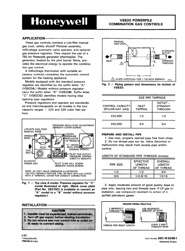
Vs5810 vs5820 millivolt gas valve 5 69 1024 5 fig. Millivolt system wiring diagram without quick drop out thermocouple. July 20 2018 by larry a. Wiring diagram images detail.


