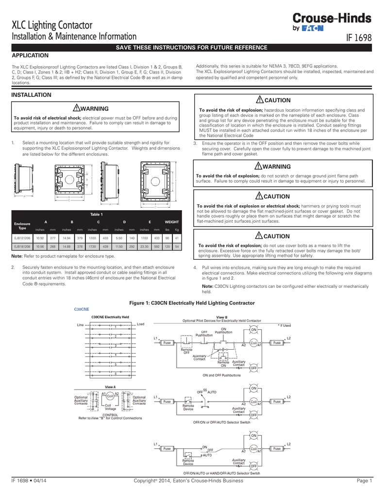
Eaton C30cne Lighting Contactor Wiring Diagram

The mechanically held operation ensures that the contactor will not switch to off during control power failure.
Eaton c30cne lighting contactor wiring diagram. A mechanically held module kit can also be added to convert the electrically held contactor into a mechanically held contactor in the field. Collection of eaton lighting contactor wiring diagram. It shows the components of the circuit as simplified forms and also the power and also signal connections in between the tools. The mechanically held operation ensures that the contactor will not switch to off during control power failure.
The c30cne20a0 is an electrically held base reversing contactor contains a 2no power pole as standard and will allow the addition of power poles to build an electrically held contactor up to 12 poles maximum. A wiring diagram is a simplified conventional photographic representation of an electrical circuit. Using the excel add in. Eaton s cutler hammer mechanically held lighting contactors are designed for industrial commercial and outdoor lighting applications where efficient control is required.
For 2 wire control ensure the two wires coming from the control module are connected across a nc auxiliary contact. 30a power pole rating up to 12 poles maximum power poles latch easily onto the base and. This video demonstrates how to install the visual t d add in in excel and then connect to the server to pull information from eaton s yukon feeder automation software directly into an excel worksheet. The c30cn 30a mechanically held lighting contactors are designed for industrial commercial and outdoor lighting applications where efficient control is required.


