Ct Shorting Terminal Block Wiring Diagram

Aboutelectricity Co Uk Wiring Diagrams Electrical Photos Movies

Air Conditioner C S R Wiring Diagram Compressor Start Full Wiring
Wiring Diagrams

Kohler Engine Electrical Diagram Craftsman 917 270930 Wiring

Automotive Alternator Wiring Diagram Automotive Electrical

Wiring Diagram 5 Pin Rectifier Wiring Diagram Jeff Sessions 2nd

Four or six pole shorting blocks can be used in applications with up to three current transformers as shown in the diagram below which allows each current transformer lead to have an individual contact point.
Ct shorting terminal block wiring diagram. 4 pole block part. Powermonitor 5000 unit as shown. Ct shorting blocks are wired such that the negative leads of the current transformers are connected to the same node and tied to ground. Connect the other side to ia ib and ic on the meter.
Connected equipment such as the powermonitor 5000 unit without de energizing the power system. Captive hardware finger safe covers din rail mounted safer than traditional shorting blocks easier to install eig offers two options for ct shorting for meter installation. Route the ct secondary wiring through the openings in the. Ei 30ct06dr these shorting blocks are designed to be a superior.
In hindi duration. If you use a 4 terminal block in will connect to the three negative non polarity wires and ground. Use a shorting terminal block included in the 1400 pm acc accessory kit test block or shorting switch by user for ct wiring to permit safely servicing. Connect the ct polarity to one side of the terminals on the shorting block.
Why secondary of current transformer is short circuited. With our test disconnect terminal blocks based on tested weidmüller screw connection technology connecting challenges can be resolved clearly and cost effectively. Single phase meter wiring diagram. Ei 30ct04dr 6 pole block part.
If you do then wire it just like the diagram shows with the shorting block between the ct s and the meter.
Wiring Diagram For A 20 Amp 240 Volt Receptacle Electrical

10382042 290351411131929 6280744195492862235 O Jpg 1 275 1 650

Automatic Transferred Switch Ats Circuit Diagram Electrical

10 Kubota Zg23 Engine Wiring Diagram Engine Diagram In 2020

Unique Wiring Schematic Legend Diagram Wiringdiagram

Block Diagram Of Circuit Breaker Block Diagram Diagram Current

Great Wiring Diagram For Horn Relay Horn Relay Simple Wiring

12 Mercury Outboard Engine Wiring Diagram Engine Diagram In

Wiring Diagram For A 50 Amp 240 Volt Circuit Breaker Home

Wiring Diagram For Trailer Light Trailer Light Wiring Chevy

97 Blazer Ignition Switch Wiring Diagram Diagram Wire Switch

Kohler Engine Electrical Diagram Kohler Engine Parts Diagram
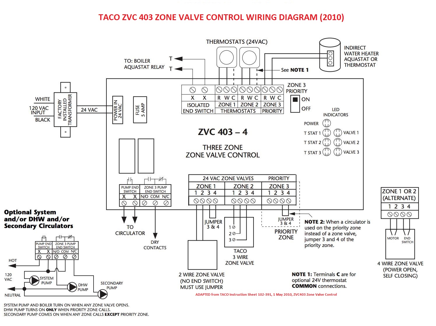
Zone Valve Wiring Manuals Installation Instructions Guide To
