Web Analytics Made Easy -
StatCounter

12v Linear Actuator Wiring Diagram

Linear Actuators 12 24vdc Actuator Strokes From 1 40 Linear

Linear Actuators 12 24vdc Actuator Strokes From 1 40 Linear

Door Lock Actuator Wiring Diagram Wellread Me And Power Door

Door Lock Actuator Wiring Diagram Wellread Me And Power Door

External Limit Switch Kit For Actuators Linear Actuator

External Limit Switch Kit For Actuators Linear Actuator

Automotive Alternator Wiring Diagram Automotive Electrical

Automotive Alternator Wiring Diagram Automotive Electrical

12volt Com Wiring Diagrams Diagram Wire 4runner

12volt Com Wiring Diagrams Diagram Wire 4runner

Unique System Circuit Diagram Wiringdiagram Diagramming

Unique System Circuit Diagram Wiringdiagram Diagramming

Unique System Circuit Diagram Wiringdiagram Diagramming

Other items in the wiring kit include the molex connectors fuse holders containing.

12v linear actuator wiring diagram. The rocker switch role is to manage how your actuator extends and retracts. No wonder you have just entered this webpage. The simplest process to wire a 12v linear actuator to a rocker switch is to use a wiring kit. How to wire a 12 volt linear actuator.

Today we will give you a hand in wiring the most popular and universe actuator. For example you can apply it your doorknob. Posted on november 06 2018 by anna. 12v linear actuator is the most basic and common actuator on earth.

The actuator can be wired in 2 ways. The options available for rocker switches include momentary and non momentary. Wiring the relay as shown will cause the voltage across pins 5 and 6 to change from 12v to 12v. Wiring the relay creates a half bridge.

Collection of linear actuator wiring diagram. A wiring diagram is a streamlined standard photographic representation of an electric circuit. It reveals the components of the circuit as streamlined shapes as well as the power and also signal links in between the devices. The installation kit comprises of two wires.

There the wide variety of places and situations to apply it in. The default position of the relay is when the relay is deactivated the active position is when pin 8 has 12v on it.

Pin By John Sandoval On Diy In 2020 Trailer Wiring Diagram

Pin By John Sandoval On Diy In 2020 Trailer Wiring Diagram

External Limit Switch Kit For Actuators Linear Actuator

External Limit Switch Kit For Actuators Linear Actuator

Wire Diagram Negative Door Trigger With Double Trigger Relay

Wire Diagram Negative Door Trigger With Double Trigger Relay

Wiring Diagram For Outdoor Thermostat Lennox Furnace Intended

Wiring Diagram For Outdoor Thermostat Lennox Furnace Intended

Unique Wiring Diagram For Electric Fan Relay Diagram

Unique Wiring Diagram For Electric Fan Relay Diagram

Control A Large Linear Actuator With Arduino Linear Actuator

Control A Large Linear Actuator With Arduino Linear Actuator

Wiring Color Codes For Dc Circuits Bodine Electric Motor Wiring

Wiring Color Codes For Dc Circuits Bodine Electric Motor Wiring

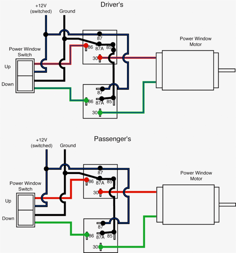
Window Motor Wiring Diagram Blurts Me With Trailer Wiring

Window Motor Wiring Diagram Blurts Me With Trailer Wiring

Using Both A Switch And Remote At The Same Time With Linear

Using Both A Switch And Remote At The Same Time With Linear

Wiring Diagram Of Motor Diagram Chart Diagram Worksheet Template

Wiring Diagram Of Motor Diagram Chart Diagram Worksheet Template

Four Channel Remote Control System 4ch Rc Remote Control

Four Channel Remote Control System 4ch Rc Remote Control

How To Create A Force Shut Off Safety System For A Linear Actuator

How To Create A Force Shut Off Safety System For A Linear Actuator

Door Lock Actuator Wiring Diagram Mes 5 Wire Great Central Locking

Door Lock Actuator Wiring Diagram Mes 5 Wire Great Central Locking

How To Use A Speed Controller With A Linear Actuator In 2020 With

How To Use A Speed Controller With A Linear Actuator In 2020 With

Source : pinterest.com